
Understanding how a Texture Analyser works – hold control
 4 minute read
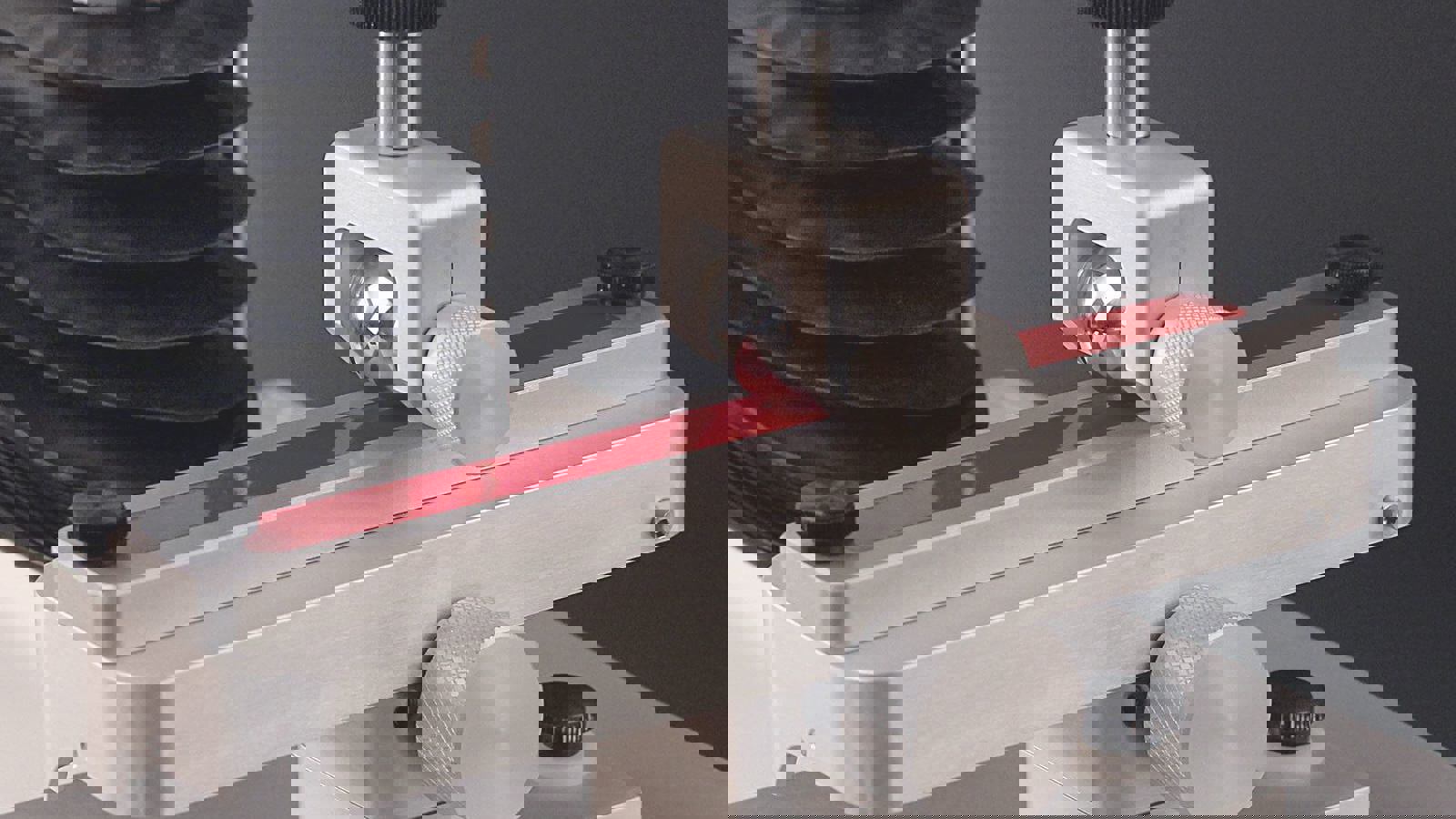
The measurement of some properties requires the ability of the Texture Analyser to perform a hold period. This involves the application of either a specified force or specified probe position for a set period of time. Force hold periods are usually controlled by a PID (proportional, integral, differential) feedback loop, with PID settings adjustable by the user for the optimisation of the hold plateau, making it as smooth and uniform as possible. Below shows graphs recorded from two adhesive tests carried out with optimised and non-optimised PID control settings. After optimisation, the hold period is distinctly more uniform, giving a more reliable hold force.

Properties that rely on these actions include the measurement of stress relaxation (a deformation is applied to a sample and held, and the change in force over time recorded), and creep (a force or stress is applied to a sample and held, with the deformation recorded over the hold period).
Hold periods also make up one stage in a more complicated test sequence. For example, food ingredient powders may be tested using an Unconfined Yield Stress measurement to investigate the effect of applied load on their flow properties, relevant to the manufacture, transport and storage phases of their lifetime. During one stage of this method, a force is applied to the powder surface and held for a specified time period. The stability and accuracy of the hold force has an influence on the measured properties of the powder compact. The same applies to any other test sequence containing a holding period.
Different types of hold test
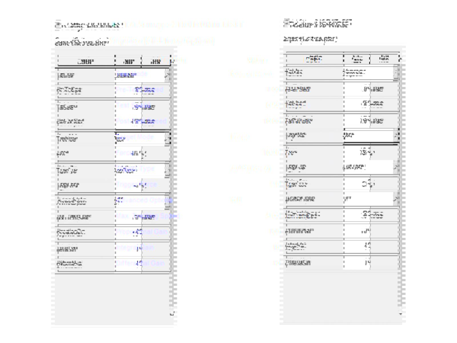
Within Exponent software there is the ability to choose tests from a library of preconfigured test sequences. There are the following 4 options for hold testing:
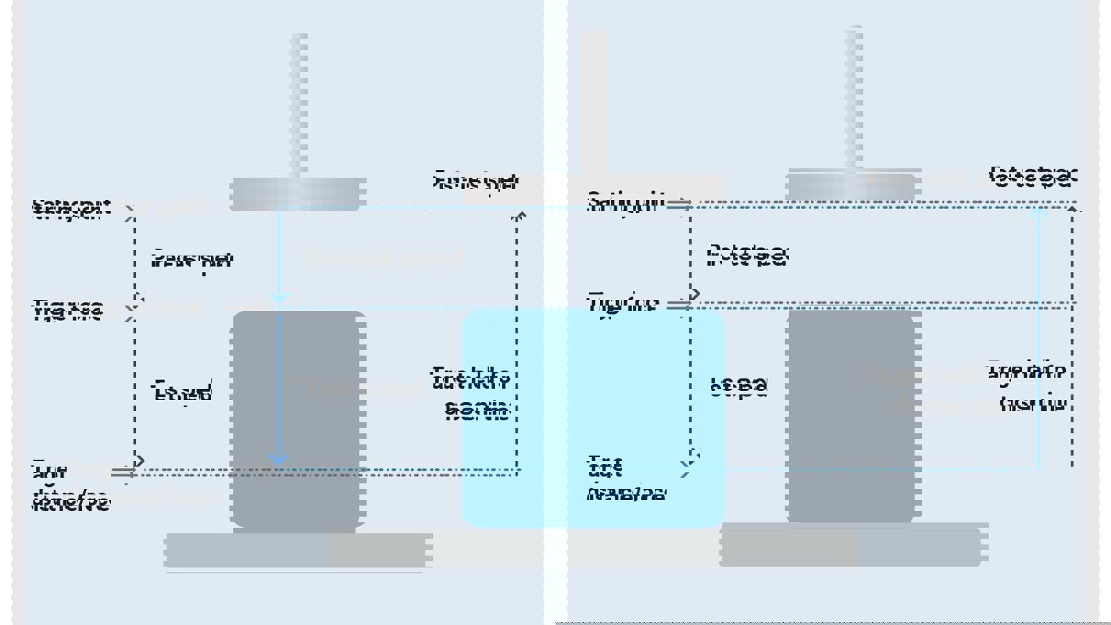
1. Hold until Time – Go to Distance
This sequence of events allows the measurement of stress relaxation properties of the product.
The probe, once triggered, advances at the selected speed until the distance (Measure Force) has been reached.
It then holds the target distance until the test runs for your chosen time (Hold Until Time). It then returns to the start position.
The test can be performed in either Compression or Tension.
2. Hold Until Time – Go to Force
This sequence of events allows the measurement of Creep Recovery properties of the product.
The probe, once triggered, advances at the selected speed until the force (measure Distance) has been reached. It then holds the target force until the test runs for your chosen time (Hold Until Time). It then returns to the start position. The test can be performed in either Compression or Tension.
Choosing PID values
For a test where you are going to a force the test settings require the choice of suitable PID settings which vary widely depending upon the sample type:
PID stands for Proportional, Integral, Derivative. PID control is used to automatically adjust a variable to hold the measurement at a set-point. The value you enter as the 'hold force' is the set point and the value that shows up on the graph is the 'measurement'.
The PID control attempts to correct the error between a measured process variable and a desired setpoint by calculating and then outputting a corrective action (in the case of the Texture Analyser this is a movement of the probe) that can adjust the process accordingly.
The basis of the system is proportional control. Adding integral control provides a means to eliminate steady-state error, but increases overshoot. Derivative control increases stability by reducing the tendency to overshoot.
Simply adding together the three required control components generates the response of the PID system and optimises the test.
In general, each type of control has the following properties on the measured variable:
Max Tracking Speed
As well as adjustments to the P, I and D parameters, TA settings has a "max tracking speed" field. This is primarily a safety feature to prevent sudden probe movements in the case of a product breaking, for instance. Although it is the force that is being controlled, this is brought about by probe movements. The max tracking speed puts a limit on the speed at which the probe can move during the PID control. 5mm/s is a good compromise in most cases.
3. Hold Until Reset – Go to Distance
The probe, once triggered, advances at the selected speed until the distance (Measure Force) has been reached.
It then holds the target distance until you press the reset button on the Texture Analyser or click on the stop test button in the toolbar (Hold Until Reset). It then returns to the start position.
The test can be performed in either compression or rension and stops when the reset button is pressed.
4. Hold Until Reset – Go to Force
The probe, once triggered, advances at the selected speed until the force (measure Distance) has been reached.
It then holds the target force until you press the reset button on the Texture Analyser or click on the stop test button in the toolbar (Hold Until Reset). It then returns to the start position.
The test can be performed in either compression or tension and stops when the reset button is pressed.
If you have lost it, request a .pdf 167 page in-depth manual to be sent to you.


